DAVIS 7627 Installation Manual
Browse online or download Installation Manual for Bridges & repeaters DAVIS 7627. DAVIS 7627 Installation manual User Manual
- Page / 48
- Table of contents
- TROUBLESHOOTING
- BOOKMARKS
- Wireless Repeater 1
- Installation Manual 1
- Circle last Repeater ID used: 2
- ABCDEFGH 2
- Table of Contents 3
- Wireless Repeater Overview 4
- Repeater Board Contents 5
- Tools for Setup 6
- Default First In Chain 6
- Jumper Position 6
- (top two pins) 6
- Repeater Architecture 9
- Single Repeater Configuration 10
- Implementing a Configuration 13
- Applying Power 14
- Single Repeater Installation 16
- Verifying Repeater ID 18
- Choosing a Location 21
- Testing a Proposed Location 22
- Repeaters 24
- Installation 26
- 2 28
- Repeaters) Installation 29
- 1 31
- Choosing Locations 32
- Testing Proposed Locations 32
- STATION NO. 5 36
- Normal Repeater Operation 39
- Error 2 (Two Flashes) 40
- Error 3 (Three Flashes) 40
- Error 4 (Four Flashes) 40
- Communication Troubleshooting 41
- Repeater Maintenance 42
- Appendix A 43
- Appendix B 44
- First in Chain Applications 44
Summary of Contents
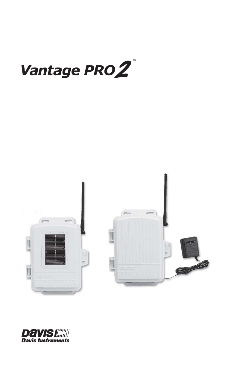
Wireless RepeaterInstallation ManualFor AC-Powered and Solar-Powered RepeatersModels 7626 and 7627
7Single Repeater ConfigurationUse a single repeater as part of a single station/single receiver setup when the distance is so great that a station alo
8The above diagram displays an example daisy-chain configuration of one station and three repeaters, creating a total line of sight transmission dista
9The diagram on the previous page shows a multiple transmitter configuration of three sta-tions and one repeater, with the repeater within a radio-lin
10See “Maximum Number of Transmitters in a Network with One Receiver” on page 9 for the receiver limitations.There is also a maximum of four repeaters
11Applying PowerApplying Battery Power (for both units)1. To view the wireless repeater board, open the shelter enclosing the wireless repeater.2. Ins
12Applying AC Power (# 7626 AC-Power units)1. To view the wireless repeater board, open the shelter enclosing the wireless repeater.2. Thread the powe
13Single Repeater InstallationA single repeater installation is used in situations where one station can not successfully communicate with a receiver,
14Optional: Changing Transmitter IDIf there is any reason that the transmitter ID needs to be set to another channel, the DIP switch should be set now
15Verifying Repeater IDThe wireless repeater also contains a DIP switch used to give the repeater a unique iden-tification in the way each station’s T
16The following diagram illustrates the Transmitter DIP and Repeater DIP switch posi-tions for a normal single repeater configuration:The STAT LED fla
Vantage Pro2™ Wireless Repeater ManualRev. C, October 18, 2005Document Part Number: 07395.238For Vantage Pro2 Wireless Repeaters: 7626, 7627Vantage Pr
17On the Console:1. Press DONE and the down arrow (-) to enter Setup Mode. Screen 1 lists active transmitters. This screen displays only the active tr
18With the setting below, the console is set up to receive an ISS station on transmitter ID 1 from repeater A.6. Press DONE to continue to the other s
19•If possible, mount the wireless repeater as high as possible (on a pole or atop a building) to overcome transmission limitations caused by the grou
20Advanced Repeater InstallationInstalling more than one repeater, or getting a repeater to receive signals from multiple stations/repeaters, follows
21Verifying Communication with a Transmitter and RepeatersAlways start verifying communication at the beginning of the chain, which is repeater A. Onc
22Use the following diagram for an example of transmitter and repeater DIP switch settings for each repeater in a daisy chain.Verifying Repeater Commu
23In this example, the console is set up to receive an ISS station with transmitter ID 1 from repeater C..4. Press DONE to continue to other screens i
24Verifying Communication with Multiple TransmittersNote: All transmitters in the network must have unique IDs in order for any repeater to communica
25Verifying Repeater Communication with a ConsoleThe console is configured the same way it is configured in a single repeater installation, except tha
26To verify that setup was successful, in the console’s Current Weather Mode:View the transmitter information displaying at the bottom of the console
iTable of ContentsWireless Repeater Overview . . . . . . . . . . . . . . . . . . . . . . . . . . . . . . . . . . . . . . . . . . . . . . . 1Included C
273. Put the repeater into Test Mode by turning on the repeater DIP Switch #4. When trying to acquire stations, the repeater goes through the followin
28Verifying Repeater Communication with a ConsoleThe console is configured the same way it is configured in a single repeater installation, except tha
29If the transmitter ID being repeated is displayed and an “X” periodically flashes in the bottom right-hand corner of the ticker tape, the transmitte
30Mounting the Wireless RepeaterThe wireless repeater can be installed on a flat surface or on a pole at the location desig-nated for installation. Us
31Installing the Repeater on a PoleRefer to the following illustration to install the repeater on a pole:1. While holding the shelter against the pole
32Console and WeatherLink ConfigurationThe Vantage Pro2 console, Weather Envoy, and corresponding WeatherLink (version 5.6 or higher) software for Van
33A number between 0 and 60 displays. A value between 30 and 60 is a sign of good signal strength. If the value is less than 20 or the field is dashed
34Configuring RepeatersWith a console or Envoy connected to your computer via serial or USB data logger:1. Select Set Transceiver from the Setup Menu.
35Note: The repeater selected for the station should be the repeater closest to the console or receiver. For exam-ple, in a daisy chain of one statio
36Maintenance and TroubleshootingNormal Repeater OperationWhen the repeater is in Test Mode (Repeater DIP Switch #4 is on) the STAT and TX LEDs should
1Wireless Repeater OverviewThe Vantage Pro2™ Wireless Repeater can be used with any Vantage Pro2 wireless sta-tion to retransmit weather data to a Van
37Error 2 (Two Flashes)ProblemStation ID is duplicated between two repeaters in a chain.Repeater BehaviorIf two repeaters are programmed to receive th
38First In Chain TroubleshootingThe three-pin header next to the Repeater ID DIP switch can enable a repeater with an ID other than A to become the fi
39Repeater MaintenanceUse the following maintenance routine on a regular basis to prolong the life of all repeat-ers in your network.•Replace batterie
40Appendix ASpecificationsComplete specifications for all of the Vantage Pro2 weather products as well as the wire-less repeater are available in the
41Appendix BFirst in Chain ApplicationsThe repeater contains a three-pin header next to the Repeater ID DIP switch that can enable a repeater with an
42Changing First In Chain Jumper PositionNote: Any repeater with ID A or that does not need to be a first in chain repeater should have the first in
43Verifying Repeater Communication with a ConsoleOn the Console in Setup Mode Screen 2: Configuring Transmitter IDs:1. Select the Transmitter ID using
44First In Chain Repeater TroubleshootingThe TX and STAT LEDs display two error codes corresponding to first in chain repeater communication problems
45First In Chain Topology with Switch and Jumper Positions11 1 2A2 2C2BAny Vantage Pro2StationRepeaterRepeaterFirst In ChainRepeaterTransmitterDIP Swi
2Repeater Board ContentsThe board contained within the repeater enclosure has the following components:TransmitterDIP SwitchesRepeaterDIP SwitchesRepe
3The components of the board are:•Solar Power Input (used on #7627 models only) — Connects the solar panel on the cover of the enclosure to the repeat
4Wireless Repeater IntroductionThe wireless repeater extends the range of a Davis Instruments weather station network and can help overcome obstructio
5Wireless Repeater Installation OverviewThe following is a overview of the steps involved for installing a repeater or series of repeaters as part of
6Repeater Configuration/ArchitectureVantage Pro2 wireless repeaters are used to enhance the transmission range and capabili-ties between a station, or
More documents for Bridges & repeaters DAVIS 7627

Related products and manuals for Bridges & repeaters DAVIS 7627
 (16 pages)
© 2020, manymanuals.com. All rights reserved. | 0.925 s |
 Manymanuals.com
 Manymanuals.de
 Manymanuals.fr
 Manymanuals.it
 Manymanuals.pl
 Manymanuals.cz
 Manymanuals.es
 Manymanuals-pt.com
Comments to this Manuals